

If anyone wants to start to build robots , This robot is for them, Its easy to do, No knowledge of programming is required, Just a little bit of electronics knowledge is sufficient to finish this robot.
Key Ingredients

1x Chassis
2x IR sensors
1x caster wheel
2x Wheels
2x Gear Motors
1x ULN 2003 IC
4x 1.5v battery or 9v battery
1x battery snap
1x battery holder
1x bread board
Spacers , stud and screws, and screw driver
Spacers , stud and screws, and screw driver
bread board connector wires
CIRCUIT DIAGRAM

What is a line following robot?
As the name suggest this robot will follow a line either black or white line.
What is the logic behind this?
This robot follows the logic of opaque and transparent surface, usually white surface reflects back the light and black surface absorb the light,
How this logic can be used in line following robot?
We can use a IR sensor , Its a pair of IR transmitter and emitter, IR rays are emits by the transmitter and received by the receiver, If the surface usually white or other color will reflect back the sensor and the receiver start to receiver by this way the sensor produce 5v as output, This output can be connected to any logic circuit to drive motor or other appliance, If the sensor meets black surface there is no reflected rays , so the logic output will be 0v.

How a IR sensor Look like?
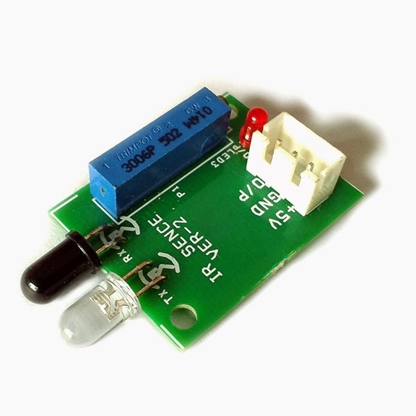
IR Sensor Circuit.

How Line Following Robot works?
This is a simple and cheap line following robot, This robot doesn't need any programming and can work without a microcontroller, hence this is a robot for a complete beginner ,
Main components of this robot is IR sensor and ULN 2003A IC
Whenever the IR sensor falls on a reflective surface or white surface it starts to give 5v as output.
ULN 2003A is a high-voltage, high- current, darlington transistor array. In this circuit it act as a switch , whenever it receives 5v as input , the output switch opens. if there is no input, switch closes.
whenever IR sensor produces 5v as output, the output pin of IR sensor is connected with the input pin of ULN 2003 IC , so the motor starts to run, if there is no output , the motor stops.

CASE 1
When sensor 1 and 2 in white surface:
In the first case both the sensors are in white surface or reflective medium, which gives 5v as output and it drives both the left and right motors .
CASE 2
When sensor 1 in white surface and sensor 2 in black surface:
In this case sensor 1 is in white surface and the sensor will produce 5v as output and only one motor rotates, which makes the robot to take a turn in right side.
CASE 3
When sensor 2 in white surface and sensor 1 in black surface
In this case sensor 2 is in white surface and the sensor will produce 5v as output and only one motor rotates, which makes the robot to take a turn in left side.
Track For LINE FOLLOWING ROBOT

We can use any track for the robot , the above one I used for the robot I made. Make sure The black line is opaque and the surface is transparent.


Simple and nice project
ReplyDeletewhat is the value of resistances in IR circuit and what is that blue and white thing in IR circuit .... ??
ReplyDeleteHi friends,
ReplyDeletei am deepu from delhi the best algorithm for line following robot or any other control system is PID (it's the most popularly used control loop), the algorithm is very simple to execute but the problem lies in fine tuning the gain parameters in the control equation. Though there are auto tuning methods, manual tuning is preferred as we will work with AVR or ardunio boards....i have purchase the kit of line following robot from
Thank you,
how can we use it for a white line follower????
ReplyDeletePlease, you can say me the key Ingredients for to make the IR sensor.
ReplyDeletecan i have circuit diagram of this. Please..
ReplyDeletei need to buy these parts please let me know where
ReplyDeletei need these parts
ReplyDeleteparts?
ReplyDeleteBro can u send me the video of preparation line to line
ReplyDelete