Monday, November 24, 2014

A simple sound activated bot, turn On when there is a sound and turn off if it hear sound again, It don't have any specific purpose just a toy with minimum intelligence lol.

This robot uses sound detecting sensor, which actually produces vibration whenever there is a noise, it cannot measure the db of the sound that producing, all it can do is to produce a signal when there is a sound .
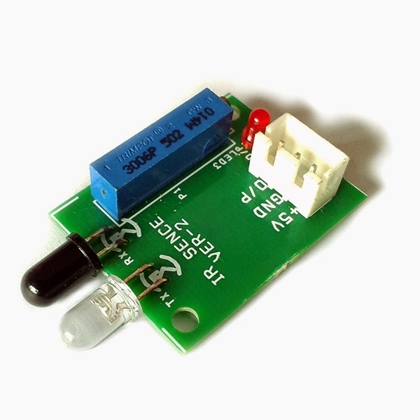


sound sensor


Arduino Program:
--------------------------------------------------------------------------------------------------------------------------

int Tomotor = 8;       // signal to motor driver
int soundsensor = 7;   // input from sound sensor

boolean state = false;

void setup()
{
  pinMode(Tomotor, OUTPUT);
  pinMode(soundsensor, INPUT);
}

void loop()
{
  if (digitalRead(soundsensor) == LOW)
  {
    delay(100);                    
    state = !state;              
    digitalWrite(Tomotor, state);  
  }
}
--------------------------------------------------------------------------------------------------------------------------


Sunday, November 23, 2014

A very simple obstacle avoiding robot using arduino , this robot uses very simple code and can accomplish the task with ease, check out the video for how the robot is working, its really simple to make not much complicated circuit. It uses HC SR-04 sensor which senses distance between the robot and object. If the distance is maximum and robot can move without colliding , the robot moves in forward direction, if the robot senses object near to it, it takes diversion and moves to the safe place and avoiding colliding to any objects around the robot,


Components Used: 

HC SR- 04 (ultrasonic sensor)
L293D Motor driver
2x Gear Motor
2x wheels
1x chasis
1x castor wheel
connecting wires
battery
Arduino Uno 


Circuit Diagram:


--------------------------------------------------------------------------------------------------------------------------
Arduino Program:

/*
 HC-SR04 Ping distance sensor:
 VCC to arduino 5v 
 GND to arduino GND
 Echo to Arduino pin 8 
 Trig to Arduino pin 9*/
#define echopin  8 // echo pin
#define trigpin 9 // Trigger pin


int maximumRange = 30;
long duration, distance;

void setup() {
  Serial.begin (9600);
  pinMode (trigpin, OUTPUT);
  pinMode (echopin, INPUT );
  pinMode (4, OUTPUT);
  pinMode (5, OUTPUT);
  pinMode (13, OUTPUT);
  pinMode (6, OUTPUT);
  pinMode (7, OUTPUT);
}

void loop ()
{

  {
    digitalWrite(trigpin,LOW);
    delayMicroseconds(2);
    
    digitalWrite(trigpin,HIGH);
    delayMicroseconds(10);
    
    duration=pulseIn (echopin,HIGH);
    
    distance= duration/58.2;
    delay (50);
    Serial.println(distance);
  }
  
  if (distance >= 30 ){
    digitalWrite(4,HIGH);
    digitalWrite(5,HIGH);
    digitalWrite(6,LOW);
    digitalWrite(7,LOW);
    delay (200);
  }
  
  else if (distance >=15 && distance <= 25) {
    digitalWrite (4,HIGH);
    digitalWrite (5,LOW);
    digitalWrite (6,LOW);
    digitalWrite (7,LOW);
    delay (1000);
  }
 else if (distance < 15){
   digitalWrite (4, LOW);
   digitalWrite (5, LOW);
   digitalWrite (6,HIGH);
   digitalWrite (7,HIGH);
   delay (1000);
   digitalWrite (4,LOW);
   digitalWrite (5,HIGH);
   digitalWrite (6,LOW);
   digitalWrite (7, LOW);
   delay (1000);
   
     
 }

}

--------------------------------------------------------------------------------------------------------------------------

For assembling the robot please check  http://learnhowtomakerobot.blogspot.in/2014/11/a-simple-line-following-robot-without.html

Wednesday, November 12, 2014

Arduino and Android control Bluetooth Robot

This post is about making a simple Android control Arduino Bot

Required Components:

Arduino Uno 
Bluetooth Module
L293D Motor Driver
2x Gear Motor
1x Chasis
A breadboard 
Connecting wires


Arduino Program
_________________________________________________________________________________

#include <SoftwareSerial.h>

SoftwareSerial BT(10, 11); //TX, RX respetively
String readdata;

void setup() {
 BT.begin(9600);
 Serial.begin(9600);
  pinMode(3, OUTPUT);
  pinMode(4, OUTPUT);
  pinMode(5, OUTPUT);
  pinMode(6, OUTPUT);

}
//-----------------------------------------------------------------------// 
void loop() {
  while (BT.available()){  //Check if there is an available byte to read
  delay(10); //Delay added to make thing stable
  char c = BT.read(); //Conduct a serial read
  readdata += c; //build the string- "forward", "reverse", "left" and "right"
  } 
  if (readdata.length() > 0) {
    Serial.println(readdata);

  if(readdata == "forward")
  {
    digitalWrite(3, HIGH);
    digitalWrite (4, HIGH);
    digitalWrite(5,LOW);
    digitalWrite(6,LOW);
    delay(100);
  }

  else if(readdata == "reverse")
  {
    digitalWrite(3, LOW);
    digitalWrite(4, LOW);
    digitalWrite(5, HIGH);
    digitalWrite(6,HIGH);
    delay(100);
  }

  else if (readdata == "right")
  {
    digitalWrite (3,HIGH);
    digitalWrite (4,LOW);
    digitalWrite (5,LOW);
    digitalWrite (6,LOW);
    delay (100);
   
  }

 else if ( readdata == "left")
 {
   digitalWrite (3, LOW);
   digitalWrite (4, HIGH);
   digitalWrite (5, LOW);
   digitalWrite (6, LOW);
   delay (100);
 }

 else if (readdata == "stop")
 {
   digitalWrite (3, LOW);
   digitalWrite (4, LOW);
   digitalWrite (5, LOW);
   digitalWrite (6, LOW);
   delay (100);
 }


readdata="";}} //Reset the variable

_________________________________________________________________________________


check the video to know how to create android app using MIT app inventor


Download Android App from here:Android App


Saturday, November 8, 2014

Arduino and Android Direction control robot.

This post is about making a simple Android control Arduino Bot


Required Components:

Arduino Uno 
Bluetooth Module
L293D Motor Driver
2x Gear Motor
1x Chasis
A breadboard 
Connecting wires


Arduino Program
_________________________________________________________________________________

#include <SoftwareSerial.h>

SoftwareSerial BT(10, 11); //TX, RX respetively
String readdirection;

void setup() {
 BT.begin(9600);
 Serial.begin(9600);
  pinMode(3, OUTPUT);
  pinMode(4, OUTPUT);
  pinMode(5, OUTPUT);
  pinMode(6, OUTPUT);

}
//-----------------------------------------------------------------------// 
void loop() {
  while (BT.available()){  //Check if there is an available byte to read
  delay(10); //Delay added to make thing stable
  char c = BT.read(); //Conduct a serial read
  readdirection += c; //build the string- "forward", "reverse", "left" and "right"
  } 
  if (readdirection.length() > 0) {
    Serial.println(readdirection);

  if(readdirection == "forward")
  {
    digitalWrite(3, HIGH);
    digitalWrite (4, HIGH);
    digitalWrite(5,LOW);
    digitalWrite(6,LOW);
    delay(100);
  }

  else if(readdirection == "reverse")
  {
    digitalWrite(3, LOW);
    digitalWrite(4, LOW);
    digitalWrite(5, HIGH);
    digitalWrite(6,HIGH);
    delay(100);
  }

  else if (readdirection == "right")
  {
    digitalWrite (3,HIGH);
    digitalWrite (4,LOW);
    digitalWrite (5,LOW);
    digitalWrite (6,LOW);
    delay (100);
   
  }

 else if ( readdirection == "left")
 {
   digitalWrite (3, LOW);
   digitalWrite (4, HIGH);
   digitalWrite (5, LOW);
   digitalWrite (6, LOW);
   delay (100);
 }

 else if (readdirection == "stop")
 {
   digitalWrite (3, LOW);
   digitalWrite (4, LOW);
   digitalWrite (5, LOW);
   digitalWrite (6, LOW);
   delay (100);
 }


readdirection="";}} //Reset the variable

_________________________________________________________________________________


Download the Android App From here: Android App

This robot work same as the voice control robot, you can refer to  link below for more details


Thursday, November 6, 2014

This post is about making a simple Android voice control Arduino Bot


Required Components:

Arduino Uno 
Bluetooth Module
L293D Motor Driver
2x Gear Motor
2x Wheel
1x Chasis
A breadboard 
Connecting wires


Arduino Program for voice control robot.
_________________________________________________________________________________

#include <SoftwareSerial.h>

SoftwareSerial BT(10, 11); //TX, RX respetively
String readvoice;

void setup() {
 BT.begin(9600);
 Serial.begin(9600);
  pinMode(3, OUTPUT);
  pinMode(4, OUTPUT);
  pinMode(5, OUTPUT);
  pinMode(6, OUTPUT);

}
//-----------------------------------------------------------------------//
void loop() {
  while (BT.available()){  //Check if there is an available byte to read
  delay(10); //Delay added to make thing stable
  char c = BT.read(); //Conduct a serial read
  readvoice += c; //build the string- "forward", "reverse", "left" and "right"
  }
  if (readvoice.length() > 0) {
    Serial.println(readvoice);

  if(readvoice == "forward")
  {
    digitalWrite(3, HIGH);
    digitalWrite (4, HIGH);
    digitalWrite(5,LOW);
    digitalWrite(6,LOW);
    delay(100);
  }

  else if(readvoice == "reverse")
  {
    digitalWrite(3, LOW);
    digitalWrite(4, LOW);
    digitalWrite(5, HIGH);
    digitalWrite(6,HIGH);
    delay(100);
  }

  else if (readvoice == "right")
  {
    digitalWrite (3,HIGH);
    digitalWrite (4,LOW);
    digitalWrite (5,LOW);
    digitalWrite (6,LOW);
    delay (100);
 
  }

 else if ( readvoice == "left")
 {
   digitalWrite (3, LOW);
   digitalWrite (4, HIGH);
   digitalWrite (5, LOW);
   digitalWrite (6, LOW);
   delay (100);
 }

 else if (readvoice == "stop")
 {
   digitalWrite (3, LOW);
   digitalWrite (4, LOW);
   digitalWrite (5, LOW);
   digitalWrite (6, LOW);
   delay (100);
 }
readvoice="";}} //Reset the variable

_________________________________________________________________________________


A step by step video tutorial for making your own android app using MIT app Inventor

Click here to download Android app

This is a simplified version of any other voice control robot, No complex coding easy to understand coding with easy algorithm.

The app is developed in such a way that it convert the voice command to text and transfer the text to the connected Bluetooth device.

The bluetooth connected on the Arduino board receives text from the Android app as characters and stored them as string to the assigned String.

There are words pre-programmed  (forward, reverse, right , left and stop) to the arduino , whenever the received text matches with the pre-programmed words ,the arduino executes the command that assigned to the words.

Arduino can connect to Laptop to monitor serial communication and check the working process and the words received by the Bluetooth.

click here to know how to make android app for voice control robot and other devices

Sunday, November 2, 2014

A Light Following Robot Without Microcontroller


Required Components :

1x Castor Wheel
2x wheels
2x Gear Motors
1x LDR sensor
1x Chassis 
1x ULN2003 IC
1x  9v battery
1x battery snap
1x Breadboard and connecting wires
Spacers, stud, screws and screw driver

Circuit Diagram:


blue wire is for connecting sensors output.


LIGHT SENSOR:


LDR SENSOR CIRCUIT:
blue wire is sensor output
red wire is power supply (5v)
black wire is ground (-ve)

How to make a LIGHT Sensor From IR Sensor
Remove both the IR transmitter and Receiver, Place a LDR in the place of Receiver IR.

How This Light Following Robot Works?

Whenever the sensor detects Light, it gives 5v as logic output. The output of the sensor is connected to the ULN2003 IC input, This IC swich ON the circuit Whenever 5v is applied to the sensor input.


check the link for How to assemble components.. http://learnhowtomakerobot.blogspot.in/2014/11/a-simple-line-following-robot-without.html


This is a Fun to do robot. The robot start to move if the sensor detects flame, be cautious when using a lighter or other element using for flame.

Required Components :

1x Castor Wheel
2x wheels
2x Gear Motors
1x Flame sensor
1x Chassis 
1x ULN2003 IC
1x  9v battery
1x battery snap
1x Breadboard and connecting wires
Spacers, stud, screws and screw driver

Circuit Diagram

blue wire is for connecting sensors output.


Flame Sensor:


Flame Sensor Circuit:


blue wire is sensor output
red wire is power supply (5v)
black wire is ground (-ve)

How to make a Flame Sensor From IR Sensor


Remove the IR emitter by cutting out from the pcb. IR transmitter which usually marked as (Tx) in the sensor pcb. If the IR transmitter removed from the pcb, this sensor act as a flame detector.

How This Flame Following Robot Works?

Whenever the sensor detects flame, it gives 5v as logic output. The output of the sensor is connected to the ULN2003 IC input, This IC swich ON the circuit Whenever 5v is applied to the sensor input.


If anyone wants to start to build robots , This robot is for them, Its easy to do, No knowledge of programming is required, Just a little bit of electronics knowledge is sufficient to finish this robot.

Key Ingredients 

1x Chassis 
2x IR sensors
1x caster wheel
2x Wheels
2x  Gear Motors
1x ULN 2003 IC
4x 1.5v battery or 9v battery
1x battery snap
1x battery holder  
1x bread board
Spacers , stud and screws, and screw driver
bread board connector wires

CIRCUIT DIAGRAM


What is a line following robot?
As the name suggest this robot will follow a line either black or white line. 

What is the logic behind this?
This robot follows the logic of opaque and transparent surface, usually white surface reflects back the light and black surface absorb the light, 

How this logic can be used in line following robot?
We can use a IR sensor , Its a pair of IR transmitter and emitter, IR rays are emits by the transmitter and received by the receiver, If the surface usually white or other color will reflect back the sensor and the receiver start to receiver by this way the sensor produce 5v as output, This output can be connected to any logic circuit to drive motor or other appliance, If the sensor meets black surface there is no reflected rays , so the logic output will be 0v.


How a IR sensor Look like?

IR Sensor Circuit.


How Line Following Robot works?

This is a simple and cheap line following robot, This robot doesn't need any programming and can work without a microcontroller, hence this is a robot for a complete beginner ,

Main components of this robot is IR sensor and ULN 2003A IC

Whenever the IR sensor falls on a reflective surface or white surface it starts to give 5v as output.
ULN 2003A is a high-voltage, high- current, darlington transistor array. In this circuit it act as a switch , whenever it receives 5v as input , the output switch opens. if there is no input, switch closes.

whenever IR sensor produces 5v as output, the output pin of IR sensor is connected with the input pin of ULN 2003 IC , so the motor starts to run, if there is no output , the motor stops.


CASE 1
              When sensor 1 and 2 in white surface:

In the first case both the sensors are in white surface or reflective medium, which gives 5v as output and it drives both the left and right motors . 

CASE 2
             When sensor 1 in white surface and sensor 2 in black surface:

In this case sensor 1 is in white surface and the sensor will produce 5v as output and only one motor rotates, which makes the robot to take a turn in right side.

CASE 3
            When sensor 2 in white surface and sensor 1 in black surface
In this case sensor 2 is in white surface and the sensor will produce 5v as output and only one motor rotates, which makes the robot to take a turn in left side.


Track For LINE FOLLOWING ROBOT


We can use any track for the robot , the above one I used for the robot I made. Make sure The black line is opaque and the surface is transparent.